Technology

What is a carbon nanotube?

Carbon nanotubes are cylindrical particles made of carbon atoms covalently bonded in hexagonal shapes. Carbon nanotubes diameters can be as small as 1 nanometer and their length up to several centimeters. When composed of multiple concentric cylinders of carbon atoms, they are called multiwall carbon nanotubes. If made of only one cylindrical wall, they are called singlewall carbon nanotubes.

Read more Read less

A carbon nanotube (CNT) is a tube-shaped material, exclusively composed of carbon atoms, having a nanometric diameter. A nanometer is one billionth of a meter, or about one ten-thousandth of the thickness of a human hair. The graphite layer can be visualized somewhat like a rolled-up chicken wire with a continuous unbroken hexagonal mesh and carbon atoms at the apexes of the hexagons. With action of van der Waals forces, CNTs have a tendency to cluster into bundles or agglomerates. Consequently, commercially available CNTs look like a black powder (macro scale).

technology-1-multiwall-carbon-nanotubes

Figure 1: NC7000™ multiwall carbon nanotubes. From left to right: macro scale, microscopic scale, nanoscale.

CNTs exist in many structures, differing in length, diameter, helicity type and number of walls. Their electrical characteristics differ depending on these variations, acting either as metals or as semiconductors.

Carbon nanotubes are classified in two main groups:

  1. Singlewall carbon nanotubes (SWCNTs).  The structure of a SWCNT can be visualized as a single layer of graphite (i.e. graphene) which is rolled into a seamless cylinder. SWCNT has one single cylindrical wall. SWCNTs diameters are in average from 1 to 5 nm and length superior to a few µm.
  2. Multiwall carbon nanotubes (MWCNTs).  MWCNTs can be visualized in the form of a coaxial assembly of imbricated SWCNTs. The MWCNTs’ diameters are typically in the range of 5 nm to 50 nm and length from µm to cm.

technology-2-Nanometric-illustration-of-SWCNT

Figure 2: (A) Nanometric illustration of SWCNT; (B) Nanometric illustration of MWCNT.

MWCNTs are easier to manufacture at industrial scale compared to SWCNTs. MWCNTs structure exhibits greater complexity and variety. The challenge in producing SWCNTs in metric tons as compared to MWCNTs is reflected in the SWCNT price, which currently remains 100 fold higher than MWCNT.

MWCNTs present therefore a higher performance/cost ratio compared to SWCNTs.

Check detailed case studies or references in Expertise Center.

What are the properties of a carbon nanotube?

A carbon nanotube is an outstanding material with intrinsic transport and mechanical properties. At the particle level, it is as electrically conductive as copper, five times stronger than steel, more thermally conductive than diamond and has a low density. Those intrinsic properties make them accurate product for nanoelectronic devices.

Read more Read less

The intrinsic mechanical and transport properties of carbon nanotube (CNT) are remarkable.

technology-3-icon1 Five times stronger than steel
technology-3-icon2 As electrical conductive as copper
technology-3-icon3 1.5 times more thermal conductive than diamond

Table 1 shows that CNTs present a unique combination of low density (lightweight material), stiffness (young modulus, E), tensile strength and tenacity compared to other fiber materials which usually lack one or more of these properties.

Table 1. Mechanical properties of industrial engineering fibers

Fiber material Young modulus, E [TPa] Tensile strength [GPa] Strain at break [%] Density [g/cm³]
Carbon nanotube 1 10-60 10 1.3-2.0
Carbon fiber – PAN 0.2-0.6 1.7-5.0 0.3-2.4 1.7-2.0
Carbon fiber – Pitch 0.40-0.96 2.2-3.3 0.27-0.60 2.0-2.2
High Speed Steels fiber 0.2 4.1 <10 7.8
Dupont® Kevlar 49 0.13 3.6-4.1 2.8 1.4
E or S glass fiber 0.07-0.08 2.4-4.5 4.8 2.5

Table 2 shows that CNT present a unique combination of low density (lightweight material), very high current density and high electrical conductivity.

Table 2. Electrical Properties of Industrial Conductive Materials

Fiber material Electrical resistivity [Ω.m] Max current density [A/m²] Density [g/cm³]
Carbon nanotube alone 10 10ⁱⁱ 1.3-2.0
Carbon nanotubes fibers 10 10⁵ 1.3-2.0
Copper 1.7×10 10⁷ 8.9
Aluminum 2.7×10 10⁸ 2.7

Table 3 shows that CNT present a unique combination of low density (lightweight material), very high thermal conductivity.

Table 3. Thermal properties of industrial conductive materials

Fiber material Thermal conductivity [W/mK] Density [g/cm³]
Carbon nanotube up to 6000 1.3-2.0
Diamond 3320 3.5
Carbon fiber – Pitch 1000 2.0-2.2
Copper 400 8.9
Aluminum 237 2.7

Intrinsic properties of carbon nanotubes make them ideal for nanoelectronic devices.

Nanocomposites: how carbon nanotubes improve properties of other materials?

In pratical terms, the van der Waals forces lead the carbon nanotubes to appear in µ-meter sized agglomerates because carbon nanotubes have a strong tendency to stick together. In order to avail their properties to the host matrices (thermoplastics, elastomers, water, etc.), carbon nanotubes need to be adequately disentangled/dispersed during processing. The optimum disentanglement/dispersion of carbon nanotubes is a key element to reach high performance nanocomposites.

Carbon nanotubes are ideal multifunctional carbon additives to improve materials performances.

Read more Read less

Carbon nanotubes (CNTs) agglomerates in powder form are rarely used as such except for specific applications such as filtration systems or sensors.

They are generally embedded in a matrix and will partially transfer their outstanding properties to the host matrix. The matrix could be any material such as a thermoplastic, rubber, water, metal, ceramic and so on. CNTs appear in µ-meter sized agglomerates because carbon nanotubes have a strong tendency to stick together due to van der Waals forces. CNTs need to be disentangled to improve specific properties of the host matrix. Dispersion equipment used will depend on the host matrix. The optimum dispersion of CNTs is a key element to reach high performance nanocomposites.

CNTs improve specific properties of the host matrix (e.g. electrical conductivity) with a lesser impact on other properties (e.g. mechanical properties) than other carbon fillers due to much lower loading required. Carbon nanotubes are ideal multifunctional carbon additives to improve materials performances compared to chopped carbon fibers (cCF), carbon blacks (CB), graphite or carbon nanofibers (CNF).

Table 4. Carbon fillers properties. From top to bottom: Super P®Li CB, Timerex® KS6 Graphite, Tenax® cCF, VGCF™ CNF, NC7000™ CNT.

Carbon black
Super P®Li CB

  • Diameter (nm) : 40
  • Aspect ratio : 1:1
  • Specific surface area (m²/g) : 60-80
  • Volume resistivity (Ω.cm) : 10-2
  • Thermal conductivity (W/mK) : <200
  • Tensile strength (GPa) : <0.4

Graphite
Timerex® KS6 Graphite

  • Diameter (nm) : 3000-5000
  • Aspect ratio : 1:1
  • Specific surface area (m²/g) : 10-20
  • Volume resistivity (Ω.cm) : 10-4
  • Thermal conductivity (W/mK) : <600
  • Tensile strength (GPa) : <0.4

Carbon Chopped Fibers
Tenax® cCF

  • Diameter (nm) : 106
  • Aspect ratio : 1:6
  • Specific surface area (m²/g) : 20
  • Volume resistivity (Ω.cm) : 10-3
  • Thermal conductivity (W/mK) : 20 (axial)
  • Tensile strength (GPa) : 3.8

Carbon nanofibers
VGCF™ CNF

  • Diameter (nm) : 150
  • Aspect ratio : 10-100:1
  • Specific surface area (m²/g) : 13
  • Volume resistivity (Ω.cm) : 10-4
  • Thermal conductivity (W/mK) : 1200
  • Tensile strength (GPa) : <10

Carbon nanotubes
NC7000™ CNT

  • Diameter (nm) : 9.5
  • Aspect ratio : 100-1000:1
  • Specific surface area (m²/g) : 250-300
  • Volume resistivity (Ω.cm) : 10-4
  • Thermal conductivity (W/mK) : >3000
  • Tensile strength (GPa) : 10-60

Graphene nanoplatelets and SWCNTs are not available at the industrial scale.  Performance results integrated in host matrices are currently demonstrated only at lab scale.

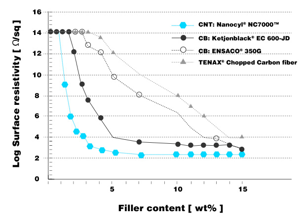
Figure 1 demonstrates the low electrical conductivity percolation threshold of carbon nanotubes compared to other carbon conductive additives.

Figure 1. Surface resistivity of carbon-filled polycarbonate compounds. Source: Nanocyl conductivity measurements.
technology-5-conductive-polycarbonate-compounds

Carbon nanofibers (CNF) and high conductive expanded graphite are not present in the graph because they are used in specific applications.

Here below is a brief description of the properties improved by carbon nanotubes. Those statements are strongly dependent on the dispersion processes, the type of polymer and even often on the polymer grade.

In thermoplastics, CNTs bring electrical conductivity with a low percolation threshold (between 0.5 wt% and 4.5 wt% depending on the thermoplastic and the dispersion processes). In general, CNTs are more easily dispersed in polar thermoplastics. The main advantage of CNTs is that they affect less the mechanical properties (e.g. elongation at break) than other conductive fillers such as carbon blacks or graphite. This is due to the high aspect ratio of CNTs resulting in a very low amount of CNTs needed to reach a specific conductivity. CNTs increase more the viscosity than CB at equal loading, but the much lower quantities of CNTs required render the processing better in most cases or comparable. CNTs concentration below 1 wt% in thermoplastics improves elongation at break and impact resistance without affecting tensile strength and keeping the thermoplastics electrically insulating. CNTs in thermoplastics offer additional improvement in cleanliness, thermal dissipation, recyclability, flame retardancy, black tinting and UV resistance.

In elastomers, CNTs improve electrical conductivity with a low percolation threshold (between 1 and 4 phr depending on the elastomer and the dispersion processes). CNTs have a stronger reinforcing factor than any other additives such as carbon blacks and silicas. Nevertheless, a synergetic effect between CNT and carbon blacks is generally observed. The combination of CNTs and carbon blacks simultaneously improves tensile strength and elongation at break compared to raw elastomers. In general, CNT/CB elastomers present higher abrasion resistance, higher thermal dissipation and good chemical resistance resulting in extended lifetime and contributing to the development of more durable products. CNT/cast PU composites generate no skid marks. CNT/silicones coatings present a nanostructured surface conducting to a fouling release effect.

In epoxy and acrylic resins, CNTs improve electrical conductivity with a low percolation threshold.  In carbon or glass fiber reinforced polymers, while the planar conductivity is brought by PAN or pitch carbon fibers, CNTs strongly increase the through thickness conductivity (z-axis) protecting structural composites from delamination due to lightning strikes.

Carbon nanotubes in those resins generally increase crack resistance.  In carbon or glass fiber reinforced polymers, grinded carbon nanotubes/thermoplastics added between the PAN carbon fibers layers increase compression after impact.

In water and solvents, carbon nanotubes bring electrical and thermal properties. Coatings containing such CNT dispersions have improved electrical, thermal and crack resistance/propagation properties.

In metals and ceramics, carbon nanotubes improve thermal and mechanical properties.

Check detailed technical case studies available in Expertise Center.

Check also the different families of formulated products in the Section Products.

What are the carbon nanotubes applications?

Nanocomposites containing carbon nanotubes push materials to new limits of performances allowing more sustainable solutions to emerge in different markets: transportation (automobile, aeronautics, maritime), energy (lithium-ion batteries, flow batteries and super-capacitors), electronics (electronic packaging, EMI shielding), sport goods and industrial solutions. This is a non-exhaustive list of markets since new applications are regularly discovered.

Read more Read less

technology-applications

Carbon nanotubes (CNTs) improve different properties in a large variety of materials which are themselves used in a large set of applications, such as:

  • Conductive plastics to improve safety in transport market, recyclability and cleanliness in electronics market
  • High performance carbon or glass fibers reinforced polymers in automotive, aeronautics and sport goods markets
  • Improved rubbers for time and conveyor belts
  • Fouling release marine coatings
  • Lithium-ion batteries with improved lifetime
  • Nanosensors to detect harmful gases
  • Flexible heating elements
  • EMI shielding
  • Corrosion protection coatings
  • Super-capacitors
  • Organic light-emitting transistors for large flat-panel displays
  • Water filters
  • Flexible thermoelectric or piezoelectric devices
  • Heat exchangers
  • Extra strong fibers

Check detailed technical case studies or references in Expertise Center.

How are carbon nanotubes produced?

Catalytic Chemical Vapor Deposition (CCVD) method is the main current method allowing an industrial scale production of carbon nanotubes with high purity.

Read more Read less

There are three main methods to produce carbon nanotubes [Nanotechnology: Basic Science and Emerging Technologies”, M. Wilson et al, (2002)]:

  1. Arc discharge method. This method creates CNT through arc-vaporization of two carbon rods placed end to end, separated by approximately 1 mm, in an enclosure that is usually filled with inert gas at low pressure.
  2. Laser vaporization method. In this method, CNTs are prepared by laser vaporization of graphite rods with a 50:50 catalyst mixture of cobalt and nickel at 1200°C in flowing argon, followed by heat treatment in a vacuum at 1000°C to remove the C60 and other fullerenes. 
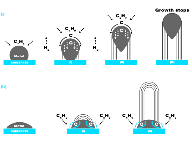
  3. Catalytic Chemical Vapor Deposition (CCVD) method. The process illustrated in the Figure 1 consists in the decomposition of a hydrocarbon vapor into carbon and hydrogen on a catalytic surface at high temperature (600-1200°C).

technology-6-idely-accepted-growth-mechanisms

Figure 1. Widely-accepted growth mechanisms for MWCNT in CCVD process with a catalyst composed of a metallic particle and a support: (a) tip-growth model, (b) base-growth model.

Arc discharge and laser vaporization are currently the principal methods for obtaining small quantities of high quality CNTs (high crystallinity). However, both methods suffer from drawbacks. First, they involve the evaporation of the carbon source, hence complicating the upscaling of the production (yield issue). Second these vaporization methods grow CNTs in highly tangled forms, mixed with unwanted forms of carbon and/or metal species. The CNTs thus produced are difficult to purify, handle, and assemble to build nanotube-device architectures for practical applications (purity issues).

In other words, Catalytic Chemical Vapor Deposition method is the main current method allowing an industrial scale production of carbon nanotubes with high purity.